Accessories
HSE offer a large range of accessories for TEL monitors, most of which can be fitted very easily during or after the installation of an airflow monitor.
HSE offer a large range of accessories for TEL monitors, most of which can be fitted very easily during or after the installation of an airflow monitor.
The 2-pin power cord (left in photo) is used for actuator-based fume hood controllers. One end plugs into a standard U.S. power outlet (no grounding plug); the other into the Econ Microprocessor Control Box (center in photo). That box provides power for both the damper actuator and AFA 1000/E fume hood controller.
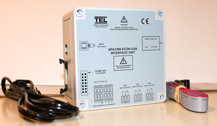
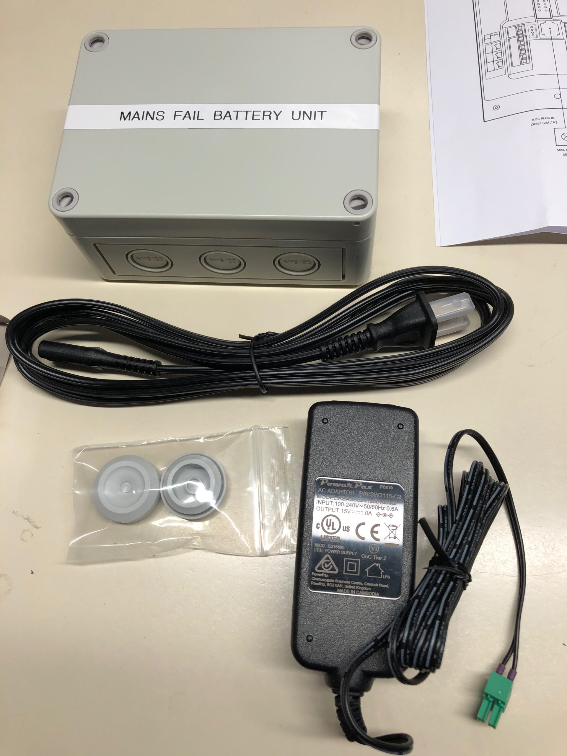
TEL AFA 1000 series monitors and controllers can be fitted with a Mains Fail unit, a battery-powered device connected to an input relay, that simply displays “mains fail” on the LCD screen for up to 16 hours. The audible alarm will sound and can be muted. All other 1000 functions stop working. In the event of a power loss, intentional or otherwise, TEL monitors remember their calibration values and other settings. Another option is to use an uninterruptible power supply.
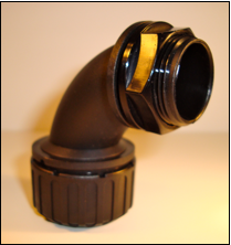
The plastic black elbow is a component of a straight inline sensor system, an option for AFA 1000 series fume hood monitors. When installed, the elbow is visible on the inside sidewall of the fume hood. On the other side, the adapter connects to the air hose, which in turn connects to the inline sensor. The elbow is mounted through a 1-inch hole in the inner lining sidewall. Like most sidewall holes, the ideal position for this hole is 4 inches back from the sash glass and 4 inches higher than the normal sash opening through the inner sidewall.
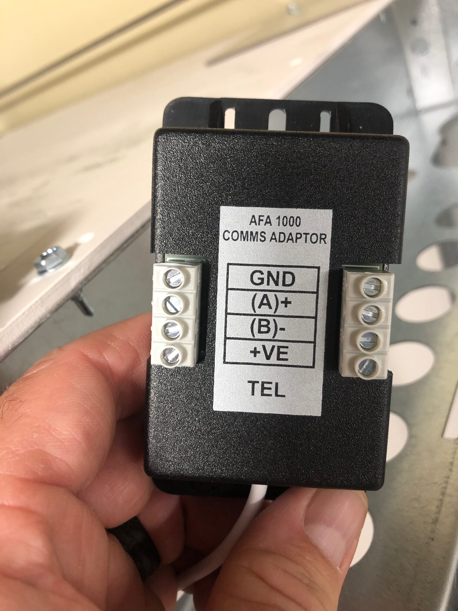
All TEL digital airflow monitors have Modbus RTU or BACnet MS/TP capabilities. Accessing these features requires the INET terminal adapter. The AFA 1000 and 4000 series on-board software allows for configuration of Modbus and BACnet communication parameters. Contact HSE for a list of available points and features.
This piece of black plastic is a component of a 90-degree inline sensor system, an option for AFA 1000 series fume hood monitors. The purpose is to prevent obstructions/foreign material from entering the air opening and corrupting the sensor. When installed, the adapter is visible on the inside sidewall of the fume hood. On the other side of the wall, the adapter connects to the inline sensor.
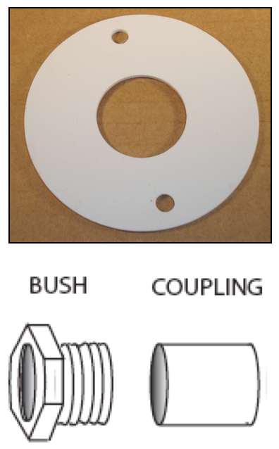
A two-part bush coupling and finishing disk fits the inner diameter of the provided air hose connecting to the back of an AFA 500 fume hood monitor or the SM6 sensor for an AFA 1000 series monitor or controller. Working with a 1-inch hole in the sidewall, the 1-inch male bush is installed from the fume hood chamber. On the interior of the sidewall, the finishing disk (optional) acts as a washer pressed flush to the inner skin. Then the 1-inch female adapter screws into the nut. Once secured, the hose fits snugly inside the bush coupling.
Inline airflow sensors work with the AFA 1000 series and include the same sensor components as the SM7 sensor supplied for standard installations. Inline sensors are installed between the inner and outer fume hood sidewalls and are not visible in the laboratory. Air hose connects to either side of the sensor, and the hose connects on one end to a hole in the sidewall and the other to the front of the hood. Like the SM7, the inline sensor connects to the rear of the monitor/controller with an RJ12 data cable.

Unlike the straight inline sensor, the 90-degree inline sensor has one side for connecting to the air hose while the other, with use of a crosshatch adapter, is connected directly to the inner sidewall hole.
A brushed stainless steel plate panel installed on the post of a fume hood and wired to the back of any TEL alarm. A provided key moves the switch between its two positions and may be removed from either position. The steel plate has the same dimensions as a standard light switch plate (2 3/4 inches wide by 4 1/2 inches tall). The switch may be used in one of two ways according to customer preference.

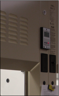
Used when installing a TEL monitor with an MK2 case style. Whereas MK3 monitors are designed for semi-flush mount installations, the mounting box facilitates surface mount installation (typically retrofit) by requiring smaller holes be cut in the fume hood post. The screws that secure the monitor to the mounting box also secure the box to the post and must not be over-tightened.
When installing an AFA 500, the air hose connecting to the onboard airflow sensor fits through the circular hole on the mounting box with enough room to accommodate the cord for the power supply.
When installing an AFA 1000, the only things that need to pass through the mounting box are the power supply cord and the SM6 data cable.
The mounting box is included with all MK2 kits at no additional cost, but boxes may be purchased separately as needed.
Dimensions
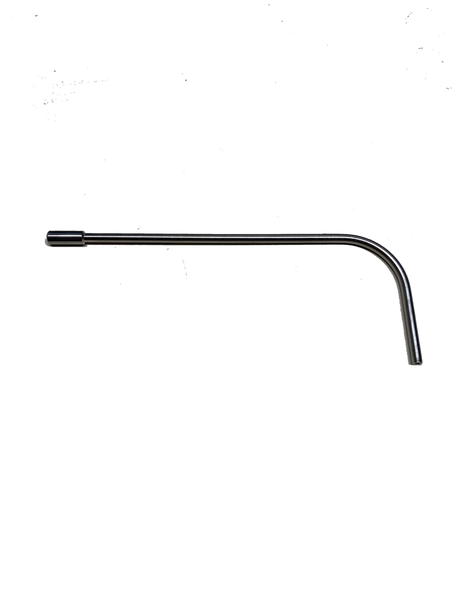
Expand your manometer kit with this accessory for reading pressure underneath closed doors and in other tight spaces. This probe from HSE offers superior durability and consistent airflow compared to rubber hose or smaller tubes. Both ends of the 1/8” tube are open so air can flow through. The straight section is roughly four inches long.
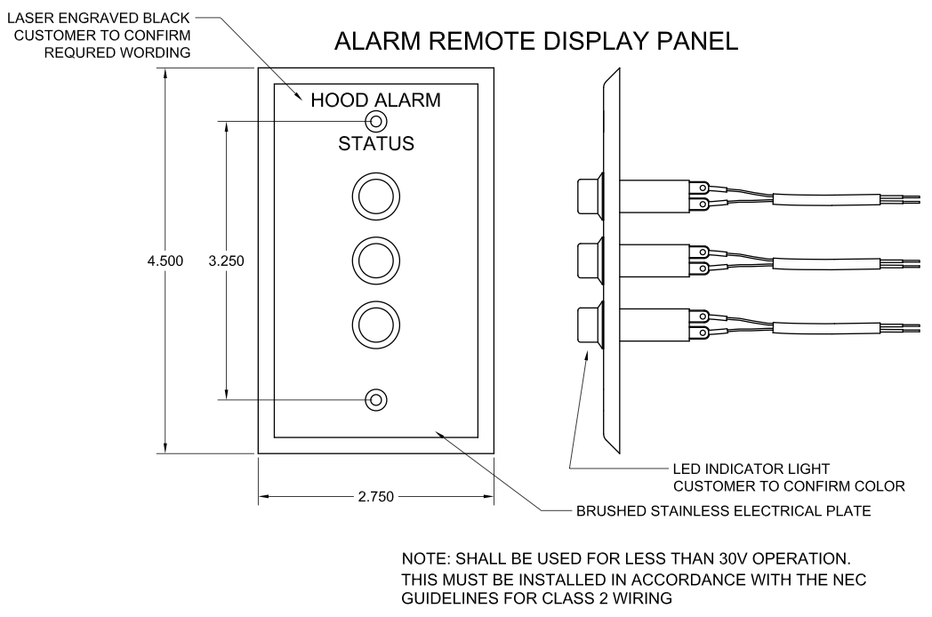
Unlike the TEL repeater, this unit is simply a brushed stainless steel plate — the size of a standard U.S. light switch plate — with an LED light connected to the alarm inside the lab. If there is an alarm condition, the light will illuminate.
Customers will specify which color LED bulb they prefer. Each panel can accommodate up to three bulbs. For labs with more than one entrance, a second identical panel can be linked to the primary panel and monitor. Also available is custom laser-engraved wording.
Each unit ships with complete wiring instructions, splice connectors and 100 feet of category 2 wire. Contact HSE to discuss any options or modifications as may be needed to suit a particular facility’s needs.
Used to copy the alarm condition of an AFA 500 or AFA 1000, it is wired to an output relay on the back of the monitor and acts as a slave to the master, the fume hood monitor — green light for normal flow, red light and horn when airflow dips below the alarm point. The repeater horn can be muted independently of the monitor.
Primarily used with AFA 1000 series monitors, the TEL repeater can be configured for AFA 500 monitors. The most common use for the repeater is on double-sash teaching hoods.
Wiring: There is no particular spec or gauge to the wire required; any standard insulated wire with a conductive area of 0.2mm² to 1mm² ought to suit; it’s whatever the individual installer has at their disposal or prefers to use when wiring into the respective terminal blocks. The terminal blocks allow for a wire size of 30 → 14 AWG.

The sensor is mounted in a fume hood sash track and wired to the back of any fume hood monitor. When the sash goes above the sensor, the fume hood enters an alarm condition. In digital fume hood monitors and controls, the display alternates between “SASH HIGH” and the face velocity. The sash high alarm may be muted by pressing the ENTER button on the monitor or controller. There is a repeat timer, so the alarm will resound after five minutes. This time can be adjusted up to 30 minutes. Click to download data sheet.

TEL auto-sash controls are designed to close the sash automatically when the operator is not present in front of the fume hood. A passive infrared sensor constantly monitors the work area in front of the fume hood. When the operator is present the sash can be operated manually via the optional Tiptronic touch sensitive feature or using an optional foot switch. If no movement is detected and the sash opening is clear, the sash will automatically close after a predetermined time. Auto open option is also available.
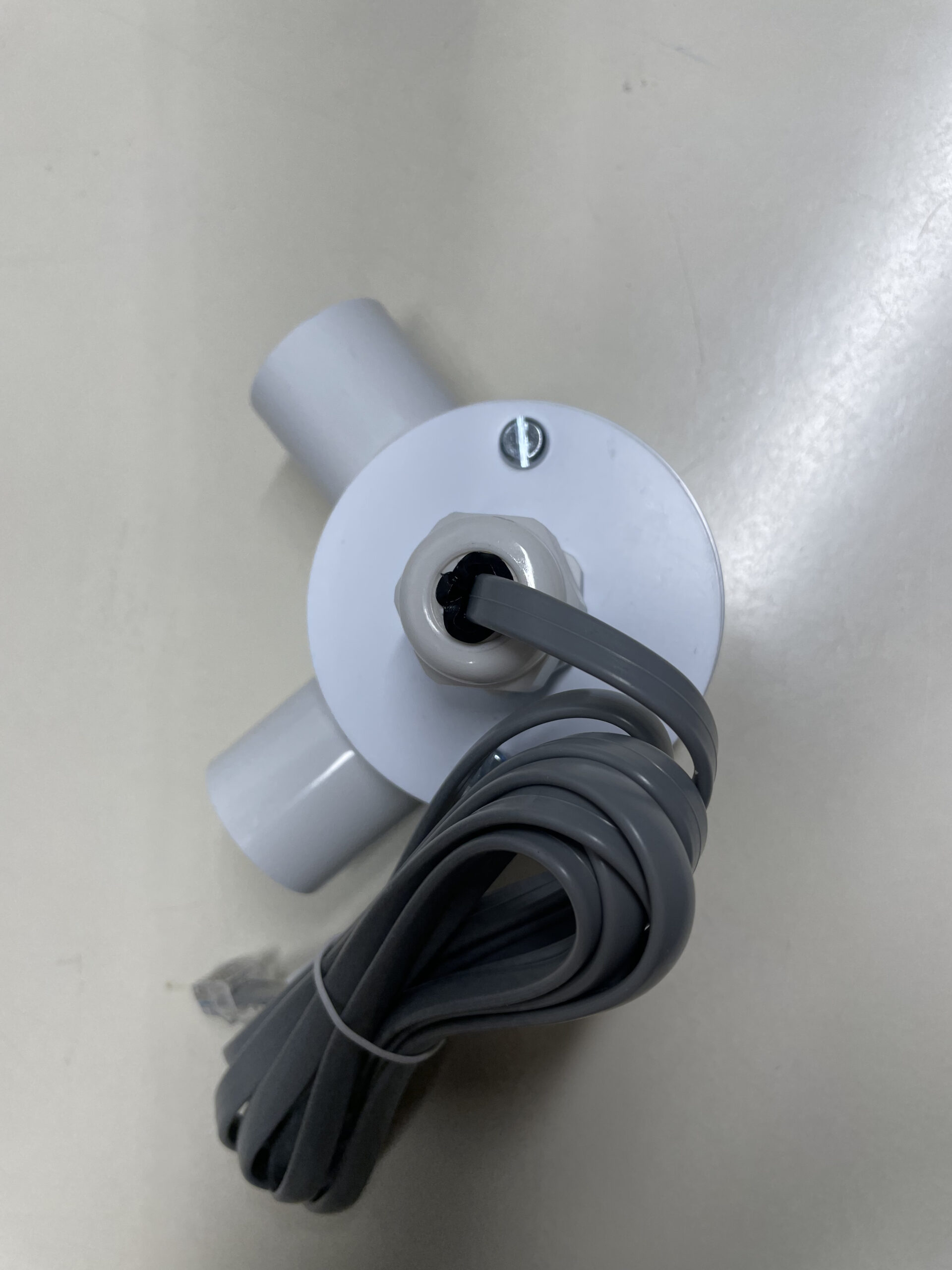
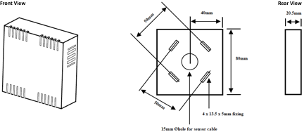
The temperature sensor can be connected to an AFA 1000 via input relay 3 in order to measure the temperature of air inside a fume hood’s working chamber. It measures a temperature range of 0 to 257 degrees F (0-125 C). The range for the low temperature alarm is 0-122 F (0-50 C). The range for the high temperature alarm is 0-257 F (0-125 C). Both the high and low temperature alarms generate audible and visual alarms and can, via the monitor’s relay output, send a signal to an external device. The enclosure is 80 mm by 80 mm by 20.5 mm. The cable to connect to the back of the monitor is 2 meters long. When configuring the monitor to accept the temperature sensor, the user must configure Input 3 Activation to analogue. Then, configure Input 3 Function to Temperature.
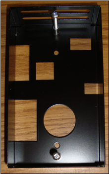
The 12150 is a duct probe designed to operate at high flows (up to 2,000 fpm). The sensor accuracy is +/- 5% over the full range. The operating temperature range is identical to that of the SM6 sensor, 55-86 F (13-30 C). There is temperature compensation for normal room environmental conditions, approximately ambient +/- 3°C. Standard cable length is two meters (approx. 6 feet); the maximum length is 40 feet. The sensor itself is 150 mm long. The intended application is for use with bio-safety cabinet airflow monitors. The probe is installed in the exhaust duct above the cabinet’s transition collar with a provided mounting plate, a 3-by-3-inch galvanized steel square. The sensor holes should be positioned in the direction of the airflow. The sensor works best when installed in the center of the duct. If it sits just on the edge of a duct it may sense turbulence. If it cannot be repositioned, a longer tube may be a solution. Download data sheet.

Contact HSE for photos and documentation of the accessories listed.